
Haas CNC machine tool and fixture setting and management (8)
Ball Milling Ball Milling Cutter is a round nose end mill with a fillet radius exactly equal to half the tool diameter. This makes the shape of the tip exactly spherical. It can also be cut with the side of the tool like an end mill. Previous Next 
Tip: The main purpose of the ball milling cutter is to machine the loft surface. The spherical profile of the tool can move along any undulating surface and can be cut anywhere along the "ball end" of the tool. Ball milling cutters can be used to cut any such surface because the ball can roll on the surface.
The cog end mill cog end mill is the same as the standard end mill, but with a replaceable carbide insert. 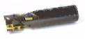
Tip: The cog end mill is used to cut metals other than cemented carbide at higher speeds. This tool has a wide range of diameters for deeper cutting. This is very useful, but when using these tools, it is best to calculate the power required for cutting. On the Haas control device, this is just a piece of cake: there is a button on the front panel labeled "HELP/CALC". Press this button to open the help menu and press again to open the calculator function. Use the PAGE UP/PAGE DOWN button to scroll between the following three pages: Trigonometry Help, Circular Interpolation Help, and Milling Help. Each page has a simple calculator in the upper left corner. On the Milling Help page, you can solve three equations:
1. SFM = (tool diameter [inch]) * RPM * 3.14159 /12
2. (chip load [inch]) = (feed rate [inch / min]) / RPM / slot number 3. (feed rate [inch / min]) = RPM / (pitch)
When using these three equations, you can enter known parameters and the control device will calculate and display the remaining unknowns. When calculating the power required for cutting, you must enter RPM, feed rate, number of slots, depth of cut, cutting width and select a material from the menu. If you change any of the above values, the calculator will automatically update the power required for cutting.
The next step to consider when selecting a tool is the material being cut. The most common cutting materials in the metalworking industry can be divided into two categories: iron-free and ferrous materials. Iron-free materials include aluminum and aluminum alloys, copper and copper alloys, magnesium alloys, nickel and nickel alloys, titanium and titanium alloys. Common ferrous materials include carbon steel, alloy steel, stainless steel, tool steel, and iron-containing casting materials such as cast iron. Non-ferrous metals are soft and easy to cut, except for nickel and titanium. Ferrous metals are usually hard and difficult to cut.
Tool material is the most important consideration when selecting a tool. Most of these tools use three basic materials: high speed steel, hard alloy, and carbide cogs. Almost all of these basic tool materials can be used to cut a variety of materials. The difference is only in performance. High-speed steel cutters have very high hardness but poor wear resistance. Cemented carbide has very good wear resistance but is prone to chipping. Carbide is suitable for cutting materials at higher speeds and feed rates, but at a higher price. Carbide cog cutters are ideal for high volume production because there are multiple cutting edges on each cog. Once a cutting edge has worn out, you can index to another cutting edge. After all cutting edges have been used, simply replace the cogs instead of the entire tool.