Insertion force test machine test example operation instructions

Insertion and Pull Force Testing Machine Operation Example Instructions One: Insertion Force Test 1. Set the movement mode to "two-way measurement" with a speed range of 1–300 (standard machine speed). The number of tests can be set between 1 and 10,000,000. Make sure to "start measuring position" and check for the origin before starting. 2. Insert the male and female connectors of the test product into the clamps. Ensure the clamps are vertical and the automatic centering device is near the center position. Avoid any misalignment that could affect the automatic centering function or damage the device. 3. Zero the load and press the move button on the panel to separate the male and female ends slightly, without fully removing them. Monitor the display to ensure smooth movement. 4. Set the test stroke to be slightly less than the actual stroke, around 0.1–0.2 mm. 5. After setting all parameters, click "File" > "Pre-set Storage" to save the file. The filename must only contain letters, numbers, periods, or hyphens — no spaces allowed. 6. Start the test on the screen. If the stroke cannot be found automatically, use a height gauge to measure the insertion stroke of the male plug. Adjust the position of the connectors and set the stroke accordingly. Ensure the stroke does not exceed the actual measured value. The starting position is also critical for accurate results. Two: Break Test 1. Clamp the test product into the upper or lower clamp and adjust the height to ensure proper grip. 2. Select "Break Test" mode. Set the stroke based on the actual length of the product to allow it to be fully pulled out. 3. Adjust the speed and number of cycles, then save the file. 4. Return to zero and clamp the product again. **Do not return to zero after clamping.** 5. Perform the test on the screen. Three: PIN Test 1. Connect the sensor interface to the test rod and lower the fixture. Adjust the position as needed. 2. Set the load measurement range to be higher than the force required to pull out the pin. The stroke range should be smaller than the distance from the pin to the insulation surface. This prevents the stroke from being too large, which might cause the actual force value to be missed during testing. 3. Choose "Load Zero Position" (only when the force starts to count) and detect the origin each time. Save the settings. 4. Begin the test. An alternative method is to use "one-way measurement" mode, with the same settings. In this case, the curve will show only the return force. Four: Constant Pressure and Tensile Test 1. Select "Constant Pressure" in the software. It will automatically open the "Force" and "Time" data frames. Enter the desired force and time values, then save the file. 2. Clamp the test product and adjust its position. 3. Start the test. When the set force is detected, the timer begins, and the test stops once the time is complete. For constant tensile force, the setup is similar, but there is no return stroke. These tests tend to be slower, usually around 30 seconds per cycle. Five: Longitudinal Force Test 1. Select the "Load Zero Position" and ensure the origin is detected each time. Set the unit to "gram." 2. Use the test rod to connect to the corresponding test head. 3. Adjust the position and test the stress at different strokes. Some customers require the stress value at the bottom point of the stroke. If needed, contact the after-sales technician for millimeter instrument support. Six: Load-Displacement Test When you need to know the deformation stroke at a specific force or the force at a certain displacement, follow these steps: 1. Set the load range to the desired force value and ensure the stroke is sufficient. 2. Select "Load Zero Position" and detect the origin each time. 3. Set the speed (usually around 30), number of cycles, and save the file. 4. Run the test and observe the waveform. The maximum value (imax) represents the required stroke. Seven: Contact Resistance Test 1. Set the parameters as you would for a regular insertion force test. 2. Select the "Insertion Point Resistance" option in the last column of the measurement items. 3. Clamp the male and female connectors using the resistance test fixture. 4. Proceed with the test. Other extended test options include anti-bending tests, peel force tests, displacement load tests for switch contacts, constant tensile life tests, and force measurements at break. These can all be performed using the Milligram brand insertion force testing machine. For detailed instructions, contact Wei Jia at 15995758658 or email [email protected]. Note that the above procedures apply only to the Milligram brand insertion force testing machine with a patent certificate. Http://news.chinawj.com.cn Insertion force test machine test example operation instructions 
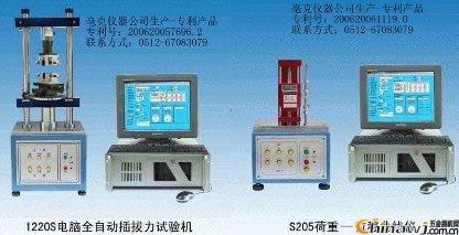
Editor: (Hardware Business Network Information Center) http://news.chinawj.com.cn Insertion force test machine test example operation instructions

Precession Vortex Flowmeter

Precession Vortex Flowmeter,Vortex Flow Meter,Precession Vortex Flow Meter,Precessing Gas Vortex Core

Jingsu Huaerwei Science and Technology Group Co.,Ltd , https://www.hewflowmeter.com